Getting Started with the DE2i-150 FPGA/Intel Atom Board on Linux
19 Feb 2017
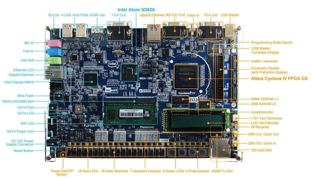
I’v been itching for a side project lately, so I decided to dig out my DE2i-150 FPGA/Intel Atom development board and start playing with it. I had previously worked with it a bit in a Windows environment, but now that I’m using Ubuntu full-time, I need to set it up in Linux. I’m going to document all the steps I took to get the board up and running in the hopes that this helps other people get going faster.
Installing Quartus
The latest version of Quartus (as of this writing) is 16.1.2 – unfortunately, template projects for the DE2i-150 board are only supported for versions 15.1.0 and 16.0.0. So I elected to download the slightly older 16.0.0 release. No big deal.
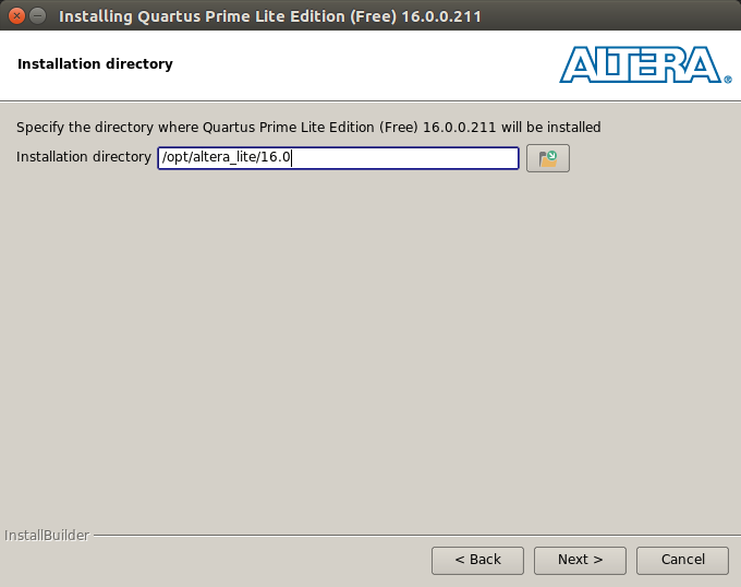
The download will come with a setup.sh script in the top-level directory. I recommend running the script as root so that you can install the application in /opt:
sudo ./setup.sh
For monolithic applications like this one, it’s typically recommended to install them in /opt:
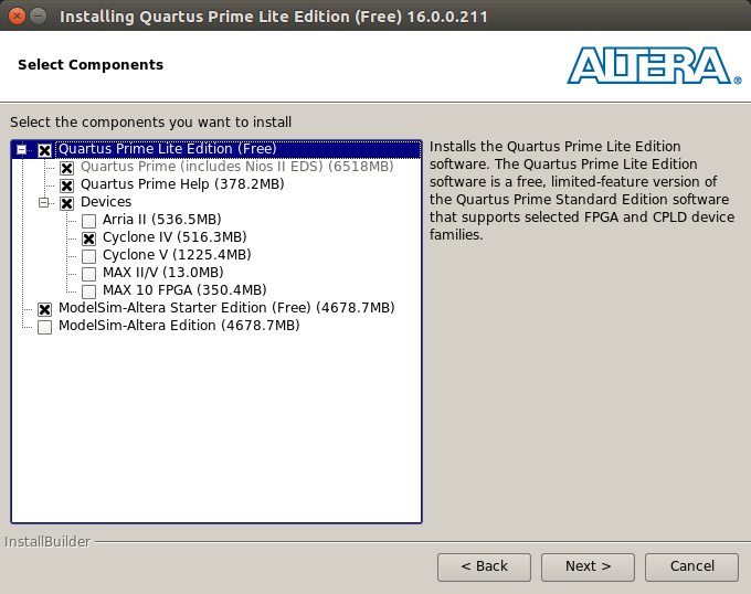
On the next screen, you’ll choose the components you want to install. Because I am working exclusively with a Cyclone IV GX board, I chose to install only Cyclone IV devices:
Proceed with the installation. Go grab something to eat while it finishes up.
Once it’s done, you can add the installation to your path to more easily start the program from the command line. On my machine, all Quartus executables are located at /opt/altera_lite/16.0/quartus/bin.
To add this to my path, I created a script in /etc/profile.d called quartus.sh:
PATH=$PATH:/opt/altera_lite/16.0/quartus/bin
At startup, this script and all others in /etc/profile.d will be sourced.
Adapt this script to your system, replacing /opt/altera_lite/16.0 with the install path you used before.
You’ll need to reboot for changes to take effect.
Configuring the USB Blaster
Now it’s time to set up the USB Blaster, which we will use to program the FPGA. Altera Quartus comes with a little daemon
called jtagd which runs in the background and provides a connection between Altera tools and the Linux
USB drivers so that Quartus can use the USB Blaster. By default, only root will be given access to the USB
device – we can leverage udev rules to give normal users access.
Power your DE2i-150 board and plug it into your computer. Type the command lsusb to show the USB devices currently
available, and look for the entry with “Altera” in the name:
...
Bus 001 Device 014: ID 09fb:6001 Altera Blaster
...
Take note of the two hex numbers separate by a colon just before “Altera Blaster”. The first of these,
09fb, is the vendor ID. This uniquely identifies Altera.
The second, 6001, is the product ID, which uniquely identifies
the USB Blaster. I suspect that these will be the same for everyone with this board, but in case,
take note of whichever vendor and product IDs you see, as you will need them in the next step.
Navigate to /etc/udev/rules.d. Create a file as root called 51-usbblaster.rules:
sudo nano 51-usbblaster.rules
Inside that file, paste the following:
# For Altera USB-Blaster permissions.
SUBSYSTEM=="usb",\
ENV{DEVTYPE}=="usb_device",\
ATTR{idVendor}=="09fb",\
ATTR{idProduct}=="6001",\
MODE="0666",\
NAME="bus/usb/$env{BUSNUM}/$env{DEVNUM}",\
RUN+="/bin/chmod 0666 %c"
Replace 09fb above with the vendor ID you saw previously,
and replace 6001 with your product ID.
This rule will be executed whenever a new USB device is plugged in.
The first four lines specify that this rule only applies to USB devices
with a certain vendor and product ID. The rule states that the device
be assigned permissions 0666, aka everyone can read and write.
IMPORTANT: At this point, unplug your USB blaster. We don’t want to activate this udev rule while it is plugged in, as this makes troubleshooting difficult. I got quite frustrated at first when my udev rule didn’t appear to be working – all because I hadn’t unplugged and replugged, which meant the rule hadn’t yet been triggered.
Run the following command to load your new udev rule:
sudo udevadm control --reload
And now plug back in your USB blaster. You can use the jtagconfig tool
to test your connection.
$ jtagconfig
1) USB-Blaster [1-3]
  028040DD   EP4CGX150
The above shows that jtagconfig successfully identified my USB Blaster.
Troubleshooting USB Blaster Setup
If you see the following when running jtagconfig
$ jtagconfig
1) USB-Blaster variant [1-3]
  Unable to lock chain - Insufficient port permissions
then your udev rule is either malformed or hasn’t been run. Try the following to fix the issue:
- Unplug your USB blaster
- Ensure your new udev rule is installed in
/etc/udev/rules.d - Run
sudo udevadm control --reloadto load your new rule. - Plug the USB blaster back in.
- Try
jtagconfigonce more.
You may see the following when running jtagconfig
$ jtagconfig
1) USB-Blaster [1-3]
  Unable to read device chain - JTAG chain broken
This can happen if you unplug and replug your USB blaster
after jtagd has been started. You should kill jtagd
sudo killall -9 jtagd
and run jtagconfig again, which will start jtagd in the background.
A similar error can occur if you unplug the USB Blaster while running
Quartus.
Programming the DE2i-150 with Quartus
Now that the USB Blaster is set up, we can create a simple program in Quartus and flash it onto the FPGA. To get going quickly, let’s use some of the baseline designs that Intel hosts online. (Compatibility issues with these design files were the motivation for installing Quartus 16.0.0 rather than the latest version.)
Link to baseline pinouts for the DE2i-150.
They host pinouts for revisions B and C of the board. To find out which revision yours is, look at the bottom left corner of the underside of the board, as shown below:
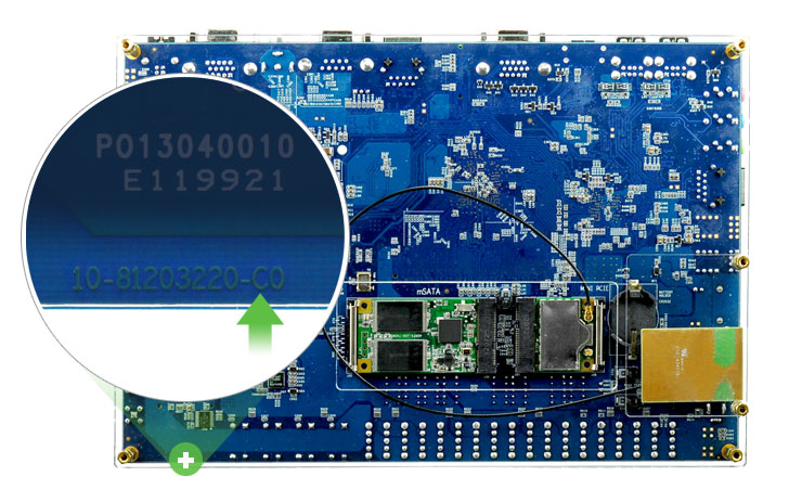
Download whichever pinout is appropriate for your board rev. You should receive a .par file.
Open quartus by running quartus at the command line, assuming the quartus
binaries have been added to your PATH. In the main window, select “New Project Wizard”.
I recommend creating a workspace folder for everything related to quartus, and creating a folder
inside of that for each project.
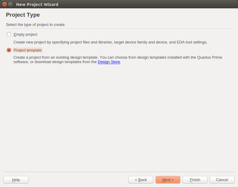
Name the project whatever you’d like, and select to use a “Project template”:
Click the link that says “add the installation directory to the design template search paths”.
In the window that pops up, click the link that says “Install design template”.
In the first box, choose the .par file you downloaded.
In the second box, choose the folder you would like to use as your quartus workspace.
For example, I created a folder called quartus in my home directory.
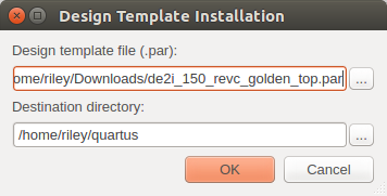
Hit OK and the .par file will be expanded and installed in the workspace. In the parent window, we will add the workspace directory to the search path.
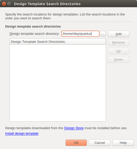
Click the “…” button to navigate to the workspace where your template was installed. Click the Add button to add the workspace to your search path. Click OK to exit this window, and you should see one template populate in the New Project Wizard.
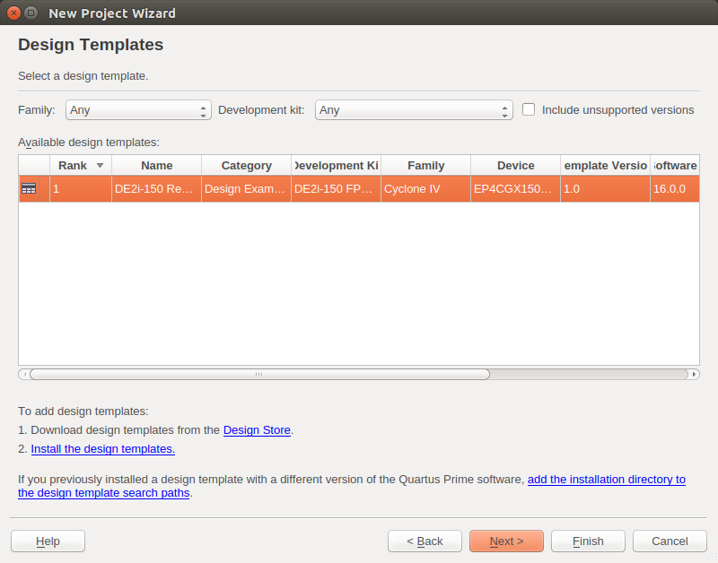
Click Next and then Finish. A new project will be created with the pinout of the board preconfigured which avoids a lot of tedious work. In the Project Navigator you’ll see one Verilog file. Open it up, and you’ll see auto-generated ports for all I/O on the board – cool!
We’ll add a small snippet of Verilog at the bottom of this file, just before
the endmodule tag, to make one of the onboard LEDs blink.
//=======================================================
//  Structural coding
//=======================================================

/* reg */
reg [32:0] counter;
reg state;

/* assign */
assign LEDG[0] = state;

/* always */
always @ (posedge CLOCK_50) begin
  counter <= counter + 1;
  state <= counter[24]; // <------ data to change
end
This will setup a counter variable which is incremented at every
positive edge of the clock input. The register state will store the
value of one of the high-order bits of the counter at every positive edge.
This state register is assigned to the first green LED, causing it to blink.
Compile the Verilog by clicking the first blue arrow at the top of the window.
 When that’s done, open the Programmer to download the program
to the FPGA.
When that’s done, open the Programmer to download the program
to the FPGA.
 In the window that opens up, click Hardware Setup…
Select your USB Blaster from the dropdown list and then close the window.
Click the Auto Detect button, at which point the FPGA should show up
in the list. If your compiled code is not already there, double click under
“File” and navigate to the .sof file you just generated.
Check the box under “Program/Configure” and then press Start over on the left.
This will load the code onto the DE2i-150, and hopefully you will see the rightmost
green LED begin to blink!
In the window that opens up, click Hardware Setup…
Select your USB Blaster from the dropdown list and then close the window.
Click the Auto Detect button, at which point the FPGA should show up
in the list. If your compiled code is not already there, double click under
“File” and navigate to the .sof file you just generated.
Check the box under “Program/Configure” and then press Start over on the left.
This will load the code onto the DE2i-150, and hopefully you will see the rightmost
green LED begin to blink!